
Ultrasonic testing: couplant, sound path and the returning echo
A returning ultrasonic signal makes sense only in the context of how sound entered the part and where it traveled. For conventional contact pulse-echo testing, start with coupling, the expected sound path and the display scale. These connections help a UT learner explain an echo before assigning it to a discontinuity.
Understand what the couplant does
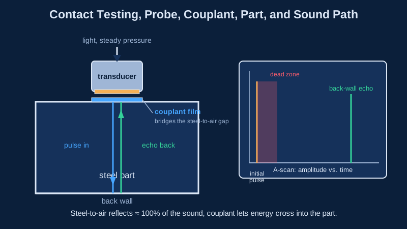
Couplant helps sound pass between a contact transducer and the test surface. Evident explains that even a very thin air gap interferes with efficient transmission at the ultrasonic frequencies commonly used for NDT. A suitable liquid, gel or paste fills that gap.
This is part of the acoustic connection, not simply a way to make the probe slide. If that connection changes, the received response can change even though the material beneath the probe has not changed.
For an actual job, couplant selection and application come from the applicable instruction and material requirements. The records below concern supplied classroom examples.
Trace the outgoing and returning path
In a simple pulse-echo thickness example, a transducer sends a pulse into a flat block and receives a reflection from the far surface. The measured travel interval includes the outward journey and the return. Turning that interval into a distance requires the appropriate sound velocity and compensation for relevant delays.
Draw the block before studying its trace. Mark the entry surface, the probe position, the expected reflecting surface, and both directions of travel. A far-surface echo is an expected response from the part boundary; the existence of an echo does not automatically establish a flaw.
Next, compare a straight path with an angled path on a second sketch. Distance along the beam and depth below the surface are different measurements. Part geometry and the assumed beam path matter when relating a response to a location.
Sources: Evident: pulse-echo travel time and thickness-gauge operation; Evident: how geometry affects sound path and reflector position.
Read the A-scan axes
An A-scan plots received echo amplitude vertically and pulse travel time horizontally. Instruments can present a distance scale derived from that timing. Check the scale and measurement labels before treating a horizontal position as a particular depth.
The horizontal position and the vertical height answer different questions. A peak farther to the right represents a later response on the same time scale. A taller peak represents a greater displayed amplitude under that setup. Neither statement, on its own, identifies the reflector.
When comparing lesson screenshots, keep the displayed scale and setup visible. A cropped trace with no units or reference information removes part of the evidence needed to explain it.
Sources: Evident: A-scan, sound-path and zero-offset terminology; ASNT: ultrasonic testing principles and displays.
Work through three classroom records
These fictional records describe supplied lesson examples, not instructions for collecting inspection data. Each compares a marked response with a reference trace from a known training block. The reference includes the probe location, a labeled path sketch, gain and a horizontal time scale. The instructor identifies the response being compared.
For each record, decide whether the evidence supports a coupling comparison, a travel-time comparison or neither. Name the fact that supports your answer. Do not fill a missing label with an assumption.
| Record | What the supplied lesson states | What the record shows |
|---|---|---|
| A: coupling comparison | The same block, marked location, probe, gain and time scale are retained. Only the coupling condition changes. | The marked response is lower, at the same labeled time position. |
| B: path comparison | Coupling, material, sound velocity and timing settings are unchanged. The supplied sketch identifies a longer outgoing-and-returning path to a known reflecting surface. | The marked response arrives later on the same labeled time scale. |
| C: incomplete comparison | Gain changed. The copied trace has no horizontal units or scale labels, and the corresponding path sketch is missing. | The peak looks taller and farther right on the copied image. |
Check your classroom-record answers
A supports the coupling comparison because the lesson identifies that as the only changed condition. Reduced sound transfer can explain a weaker received response. The unchanged time mark is a separate observation; the lower peak does not introduce a new discontinuity into the supplied example.
B supports a travel-time comparison: the later response is consistent with the longer round trip supplied by the sketch and unchanged sound velocity. The reasoning uses both the record and the drawing. A later echo alone would not identify its reflector or establish depth below the surface.
C supports neither comparison. Gain changed, so the taller peak cannot be treated as an unchanged-setup amplitude comparison. With the horizontal scale missing, farther right on a copied image cannot establish a longer travel interval. Keep the missing labels and sketch as unresolved information.
Now remove the sentence that names the changed condition from record A. Your answer must become less specific: the response differs, but the record no longer isolates the reason. This variation tests whether your explanation follows the supplied evidence or quietly adds facts.
Sources: Evident: coupling and sound-energy transmission; Evident: round-trip time and sound velocity; Evident: amplitude, gain and A-scan terminology.
Connect the explanation with your UT training
NDT Academy's current UT curriculum includes Pulse-Echo Instruments, Displays, and Controls; Couplants: Purpose, Selection, and Efficiency; Straight-Beam and Angle-Beam Contact Techniques; and Transmission Factors: Transducer, Couplant, and Material. Study these topics together so the trace stays connected to the physical example.
Before moving to another practice question, try explaining a supplied trace in three sentences: how sound enters, which path could produce the response, and what the display actually shows. Leave uncertainty visible when the example does not provide enough information.
Continue with the reference-block information exercise when you are ready to connect a supplied setup record with its named reference. For a group learning plan, the employer training page provides the team inquiry route.
The public UT sample lets you explore a real lesson before enrolling. Review formal training and completion records as part of your learning plan, with practical experience, examinations and certification requirements considered separately with your employer or Responsible Level III.
Sources and further reading
- ASNT: ultrasonic testing principles and displays
- Evident: coupling and sound-energy transmission
- Evident: round-trip time and sound velocity
- Evident: how geometry affects sound path and reflector position
- Evident: amplitude, gain and A-scan terminology
Sources checked on October 11, 2026. Follow the current requirements from your employer or certification body when planning qualification or an examination.